
You can still be the Maker you wanted to be!
I haven't been on the planet for more years than you may expect. But Ive met people, Ive known people, Ive heard stories. Stories of some as young as …


Overview of project Materials and components needed Step by Step Tutor Overview of project In this project we are going to build a circuit with…
A little history Like all other things, Integrated circuits also have a history, they didn’t just appear and are all over the place all of…
Just Imagine you create a robot or a machine or a crane which you want it to lift objects and put them at another place…


In this post I am attempting to give an overview of two main and very important things you should know when it comes to electronics,…

Resistors as we know, if not an exaggeration are the most popular electronics components in history. They play so many vital roles in all electronic…
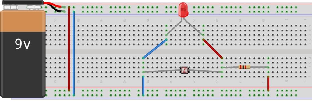
Overview Materials needed Set up Overview What you need to know; Ohms law. Voltage division. How to use the breadboard. How the LDR works. In…
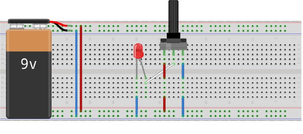
Overview Materials Set up Overview In the “toggle an LED” article you realize that your circuit had only two distinct events, a HIGH (1) thus…

Overview Materials Set up Overview Getting an LED toggled high is not a big deal until reality hits you unaware. Many students have theoretically constructed…
Please confirm you want to block this member.
You will no longer be able to:
Please note: This action will also remove this member from your connections and send a report to the site admin. Please allow a few minutes for this process to complete.