Using the dual axis analog joystick module
Where are the game center squad?
Do you remember those guys behind the UCOM game pad who would be like “oh as for me I play FIFA well with analog” and at the end of the day they would still loose the match, eiiiii?
You know what, today we will be doing something technical and fantastic with one of the joystick modules.
But firstly what did we even mean by “analog” when we referred to the game pads?
What is Ananlog?
Look here, whenever we said “analog”, we refered to those two smooth and ball-like control methods on the game pad.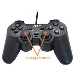 Its very true and correct but technically the word analog means more to the world of electronics and progamming, and you will be seeing that for yourself soon. Secondly what if you could use these analog joysticks to control more than just C-Ronaldo and the racing cars in the game but you could control things in real life like drones, remote control cars, robot arms, cranes and many more. Thats exactly what we are going to focus on here today so get a cup of koko by yourside and lets delve in!
Analog signals
The best way I try to differentiate between analog and digital signals is to use the example of the bulb switch and the ceiling fan regulator.
Digital signals are like the regular bulb switches we have in our houses, they can only tell the bulb to either come on or go off, they wont tell the bulb how bright or dim it should be. If a component you are working with, has a digital output pin it means that the pin can only spit out “a 1 or a 0” and nothing else.
Analog signals are different, and can be compared with the ceiling fan’s regulator. You realize that the regulator doesn’t just tell the fan to come on or off, it also tells the fan how fast or slow it should move. So in this case the regulators for fans have more control and options or choices than the switches for our light bubls.
Thats it! Analog signals actually spit out so many varying values. In all the micocontrollers you use, you might have come acorss the range of values “0 to 1023” several times and that’s actually how any analog electronic pin will express itself. 0 for the lowest and as the voltage increase it will increase accordingly to the maximum 1023.
If you want to understand more, then read shortly about this digital and analog command circuits which I worked on sometime ago.
The KY-023 dual axis joystick module
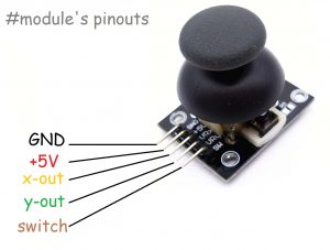 This is the particular joystick module we will be using. Of course you can break your UCOM game pad and take those in there but then you will have to do some more soldering and desoldering work in other to hack all the useful pins out. Else you can just grab one of these cheap modules from the Aaenics store and go your way already.
Dual axis means two axis. Which means the joystick can control two floating points in two separate axis. So we can say, the X and Y axis. I hope you havent forgotten your cartesian plane from primary when you started using graph sheets to draw stuff. At the end of the day the data we will extract from the x-out and y-out pins will be represented as coordinates on an x-y plane like this:
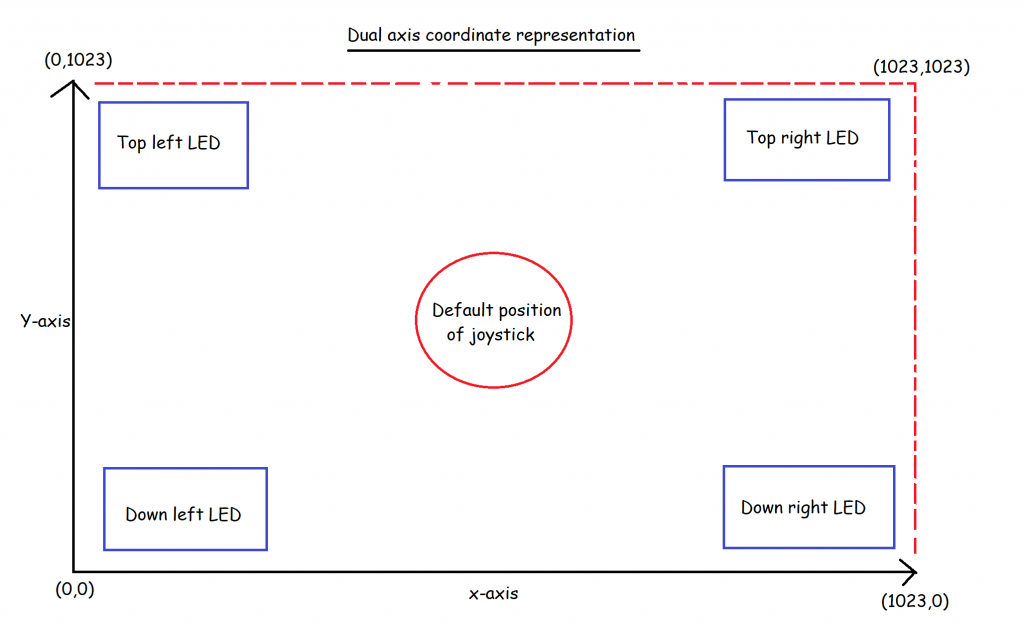
The module is very easy to configure since the labels are all inscribed already as you can see. All you need is to connect the pins to the appropriate pins on the microcontroller.
In the project below we will be using an arduino microcontroller to extract all the data we need from the joystick and also use the data to learn how to control something cool in real life. Oh am not going to worry you to control a drone or a crane now but then just a few LEDs. The concepts from here is what will lead you to control greater things out there. I can’t wait to see what you will be building around this soon.
The joystic and LEDs circuit
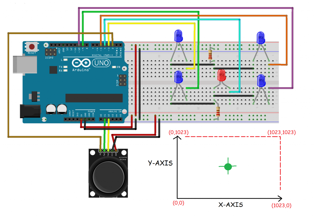
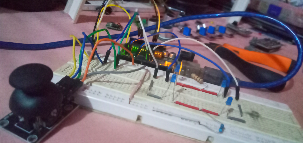
The circuit looks complex but then hei its super simple! just take your time and understand what we want to achieve here and you will be fine.
The five LEDs you see on the right are going to be controlled by the joystick. The direction the joystick will be moved will tell which LEDs or group of LEDs should come on. You can watch the video below the tutorial to see what is actually happening.
I will be showing you a trick soon which will make using the module so nice. At default, if you follow the way the module has been labeled, it will work just fine but the data extraction and logical comprehension of the x and y axis will not be cool. Even if you position your module just the way I have positioned mine in the diagram, your x-axis and y-axis will not seem right but I will show you how to make it yours.
The secrete to correct the axis.
If you position your joystick just the way mine is positioned in the layout diagram above and then you follow strictly the default pin diagram inscibed, the x axis will be substituted with the y axis and the whole graph will not be as cool as the normal xy axis graph you know. you have to change the default graph appearance and i will show you how.
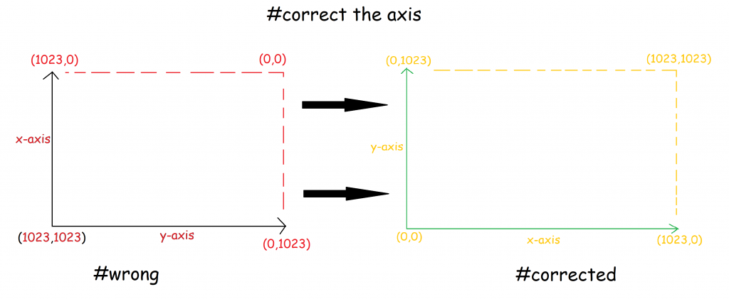
Follow these simple steps to correct the axis:
 Swap the VCC and GND pins. There are no diodes in the joystick module so just swap the VCC and GND.This will change the polarities(+ and -) of the two potentiometers inside the joystick. The potentiometers will now respond to the changes and spit out 0 to 1023 instead of 1023 to 0.
- Secondly, the x and y axis themselves have to be swapped. But you will swap them in the codes and not in the hardware(circuit).
In the codes, when you are declaring and intializing the x and y pins, you just have to swap them in there like this.
//define pins
int x = A1;//but A1 is connected to y in actual circuit
int y = A2;//but A2 is connected to x in actual circuit
you can see that in my circuit, A1 is connected to the y axis and A2 is connected to the x-axis but then in the code I have intentionally declared the opposite. This should be done in other to swap the y and the x axis on the graph.
If you do these two things then hei you are already done with the project. Yes you are done, the rest is just the codes, and as usual its right below here. Well commented and easy to understand and modify. Copy, paste in your IDE and upload to your circuit setup and you will see all the magic. Hurray!!!
Put this life in your circuit now!
/*control LEDs with the joystick module */

//define pins
int x = A1;//but A1 is connected to y in actual circuit
int y = A2;//but A2 is connected to x in actual circuit
//note that the push button on the joystick was not used in this project

//declare all 4 LEDs
int topleft = 3;
int topright = 5;
int downleft = 9;
int downright = 10;

//variable to hold the cartesian coordinate(0 to 1023 for each axis)
float xaxis;
float yaxis;


void setup() {
  pinMode(topleft, OUTPUT);
  pinMode(topright, OUTPUT);
  pinMode(downleft, OUTPUT);
  pinMode(downright, OUTPUT);

  pinMode(x, INPUT);
  pinMode(y, INPUT);

  Serial.begin(9600);
}

void loop() {
  //read x and y axis coordinates
  xaxis = analogRead(x);
  yaxis = analogRead(y);

  Serial.print(xaxis);
  Serial.print(",");
  Serial.println(yaxis);

  //coordinates at the edges*******************************
  if ((yaxis >= 900) && (xaxis <= 700) && (xaxis >= 300)) {
    digitalWrite(topleft, HIGH);
    digitalWrite(topright, HIGH);
  }
  else if ((yaxis <= 200) && (xaxis <= 700) && (xaxis >= 300)) {
    digitalWrite(downleft, HIGH);
    digitalWrite(downright, HIGH);
  }
  else if (xaxis > 900 && yaxis < 700 && yaxis > 300) {
    digitalWrite(topright, HIGH);
    digitalWrite(downright, HIGH);
  }
  else if (xaxis < 200 && yaxis < 700 && yaxis > 300) {
    digitalWrite(topleft, HIGH);
    digitalWrite(downleft, HIGH);
  }

  //coordinates at the corners*****************************
  else if (xaxis > 900 && yaxis > 900) {
    digitalWrite(topright, HIGH);
  }
  else if (xaxis < 100 && yaxis < 100) {
    digitalWrite(downleft, HIGH);
  }
  else if (xaxis > 900 && yaxis < 100) {
    digitalWrite(downright, HIGH);
  }
  else if (xaxis < 100 && yaxis > 900) {
    digitalWrite(topleft, HIGH);
  }

  //if coordinate is not mapped**********************
  else {
    digitalWrite(topleft, LOW);
    digitalWrite(topright, LOW);
    digitalWrite(downleft, LOW);
    digitalWrite(downright, LOW);
  };

} 


Responses