Introduction to NRF-24 Radio Transceiver

At some point, most Arduino DIY hobbyist will decide/want to upgrade/interface their projects to be controlled from a distance or communicate wirelessly with other micro-controllers.
They may also want to control a decorative set of room lights from the comfort of their armchair without running over cables. They could also read the temperature and humidity of their greenhouse without going close to the setup and wandering up the garden. Another use may be to control a robot from a hand-held home-built controller with a joystick (which has already been covered here)
This article is purposely based on the introduction of the NRF24 radio module and a simple NRF transmission project to introduce you to the world of wireless communication.
Having two or more Arduinos, you will be able to communicate with each other wirelessly over a distance which tends to open lots of possibilities:
- Remote sensors for temperature, pressure, alarms, much more
- Robot control and monitoring from 50 feet to 2000 feet distances
- Remote control and monitoring of nearby or neighborhood buildings
- Autonomous vehicles of all kinds
NRF-24 Features/Specs
- Communication Range 800 – 1000 meters (1 km)
- Frequency Range 2.4 GHz ISM Band
- Logic Inputs 5V Tolerant
- Maximum Air Data Rate 2 Mb/s
- Modulation Format GFSK
- Max. Output Power 0 dBm
- Operating Supply Voltage 1.9 V to 3.6 V
- Max. Operating Current 13.5mA
- Min. Current(Standby Mode) 26µA
nRF-24-L01 module Vs nRF24L01+ PA/LNA module
There are actually two(2) different types of the NRF radio modules available based upon the nRF24L01+ chip. Below are the main differences.

The first version uses an on-board antenna. This allows for a simpler version of the breakout. However, the smaller antenna also means a lower transmission range. With this version, you will be able to communicate over a distance of 100 meters approximately. But automatically, your range indoors especially through walls, will be slightly weakened.
The second version comes with a SMA connector and a duck-antenna but that’s not the real difference. The real difference is that it comes with a special RFX2401C chip which integrates the PA, LNA, and transmit-receive switching circuitry. This range extender chip along with a duck-antenna helps the module achieve a significantly larger transmission range about 1000m(1 km).

The PA stands for Power Amplifier. It merely boosts the power of the signal being transmitted from the nRF24L01+ chip. Whereas, LNA stands for Low-Noise Amplifier. The function of the LNA is to filter the signal transmitted and received for a clear communication.
How nRF24L01+ transceiver module works
RF Channel Frequency
The nRF24L01+ transceiver module transmits and receives data on a certain frequency called Channel. Also in order for two or more transceiver modules to communicate with each other, they need to be on the same channel. This channel could be any frequency in the 2.4 GHz ISM band or to be more precise, it could be between 2.400 to 2.525 GHz (2400 to 2525 MHz).
Each channel occupies a bandwidth of less than 1MHz. This gives us 125 possible channels with 1MHz spacing. So, the module can use 125 different channels which give a possibility to have a network of 125 independently working modems in one place.
Simple Hands-On DIY Project
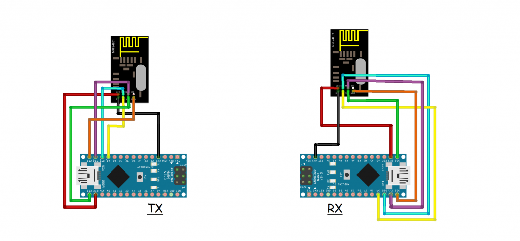
in this project we demonstrate on how to control an LED bulb with a Potentiometer or Variable Resistor from a long distance to test our wireless transmission capabilities using our NRF24 radio module

LINK TO DOWNLOAD CODE
Transmitter code here
/* 1 ch NRF 24 TRANSMITTER example.

  Module // Arduino UNO
    GND    ->   GND
    Vcc    ->   3.3V
    CE     ->   D9
    CSN    ->   D10
    CLK    ->   D13
    MOSI   ->   D11
    MISO   ->   D12
*/

//First Download  NRF24 library

#include <SPI.h>
#include <nRF24L01.h>
#include <RF24.h>


/*Create a unique pipe out. The receiver has to
  wear the same unique code*/
const uint64_t pipeOut = 0xE8E8F0F0E1LL; //IMPORTANT: The same as in the receiver!!!

/*Create the data struct we will send
  The sizeof this struct should not exceed 32 bytes
  This gives us up to 32 8 bits channals */
RF24 radio(9, 10); // select  CSN and CE  pins
struct MyData {
  byte pot_value;
};
MyData data;
/*//////////////////////////////////////////////////////*/


//This function will only set the value to  0 if the connection is lost...
void resetData()
{
  data.pot_value = 0;
}

void setup()
{
  //Start everything up
  radio.begin();
  radio.setAutoAck(false);
  radio.setDataRate(RF24_250KBPS);
  radio.openWritingPipe(pipeOut);
  resetData();
}

/**************************************************/

// Returns a corrected value for a potentiometer analog read
// It will map the value from 0 to 1024 to 1 to 255
int mapPotentiometers(int val, int lower, int middle, int upper, bool reverse)
{
  val = constrain(val, lower, upper);
  if ( val < middle )
    val = map(val, lower, middle, 0, 128);
  else
    val = map(val, middle, upper, 128, 255);
  return ( reverse ? 255 - val : val );
}

void loop()
{
  data.pot_value = mapPotentiometers(analogRead(A2), 0, 512, 1024, true);
  radio.write(&data, sizeof(MyData));
}
Receiver code here
/* 1 ch NRF 24 RECEIVER example.

  Module // Arduino UNO
    GND    ->   GND
    Vcc    ->   3.3V
    CE     ->   D9
    CSN    ->   D10
    CLK    ->   D13
    MOSI   ->   D11
    MISO   ->   D12
 */

// First Download the NRF24 library if you dont have it
#include <SPI.h>
#include <nRF24L01.h>
#include <RF24.h>

/*Create a unique pipe out. The receiver has to
  wear the same unique code*/
const uint64_t pipeIn = 0xE8E8F0F0E1LL; //IMPORTANT: The same as in the receiver!!!

/*Create the data struct we will send
  The sizeof this struct should not exceed 32 bytes
  This gives us up to 32 8 bits channals */
RF24 radio(9, 10); // select  CSN and CE  pins
struct MyData {
  byte pot_value;
};
int LED = 3;
MyData data;
/*//////////////////////////////////////////////////////*/

//This function will only set the value to  0 if the connection is lost...
void resetData()
{
  data.pot_value = 0;
}


/**************************************************/

void setup()
{
  pinMode(LED,OUTPUT);
  Serial.begin(9600); //Set the speed to 9600 bauds if you want.
  //You should always have the same speed selected in the serial monitor
  resetData();
  radio.begin();
  radio.setAutoAck(false);
  radio.setDataRate(RF24_250KBPS);
  radio.openReadingPipe(1,pipeIn);
  //we start the radio comunication
  radio.startListening();
}


//Reset the received data to 0 if connection is lost
unsigned long lastRecvTime = 0;
void recvData()
{
  while ( radio.available() )
  {
    radio.read(&data, sizeof(MyData));
    lastRecvTime = millis(); //here we receive the data
  }
}
/**************************************************************/


void loop()
{
recvData();
unsigned long now = millis();
//Here we check if we've lost signal, if we did we reset the values
if ( now - lastRecvTime > 1000 ) {
// Signal lost?
resetData();
}

Serial.print("Potentiometer: "); Serial.println(data.pot_value);
analogWrite(LED,data.pot_value);

}
Thanks for getting time to go through this wonderful and eye opening tutorial. Hope to see a project from you, based on the NRF24 radio transceiver 🙂


I’ve been wondering how to build this for a long time
Yh its interesting. There are actually many simple transmitter and receiver set out there that you can add to your RC cars project to make them wireless. This is just one of them
wooow
Then here you go, lets see your magical outcomes 🙂
Okay