Understanding RFIDs and Integrating them in your projects

The first time I saw an RFID card, my team and I were representing Ghana at the World Robot Olympiad. We lodged in a beautiful hotel and hei, all the doors to our rooms didnt have the usual key locks I had in my house hahaa. You can imagine how confused we were when the receptionist gave us some rectangular cards  and said “Take, these are your keys”😂. Applications of RFIDs are amazingly numerous and I belive at the end of this lesson you may even come up with other applicatioins we havent even thought of yet.

What are RFIDs?

RFID stands for Radio Frequency Identification and it is basically a technology that allows us to be able to store useful identity data in common objects we use everyday. These objects, that are made to carry such data are called RFID tags. An example is the rectangular card the receptionist gave to me as my key. It could even be a button, a sticker, a bracelet, the color of your dog’s chain, or just anything tangible. Though these tags may be papers or rubbers, They are manyfactured to have micro-circuits in them. The circuits in them have a small storage device that allow them to store the data they carry.

The other end of the RFID technology is the RFID reader/writer, which are also simle circuits designed to be able to read the information that are already stored in the RFID tags.

These RFID readers/writers are able to also write new informations to the tags. It means you can even store something precious in it. Think about it.

RFID tags and RFID readers communicate by means of short distance radio frequencies. They were very expensive and not common in the past but today you can grab an RFID set from the Aaenics store or you already have it if you bought an arduino kit with an RFID set already inside.

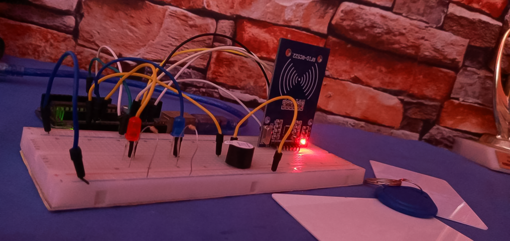
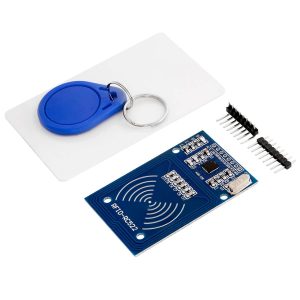
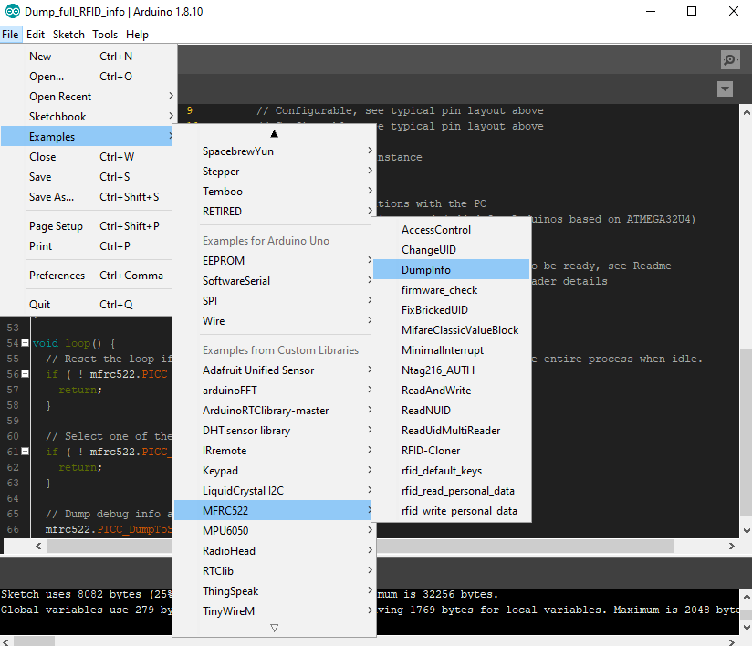
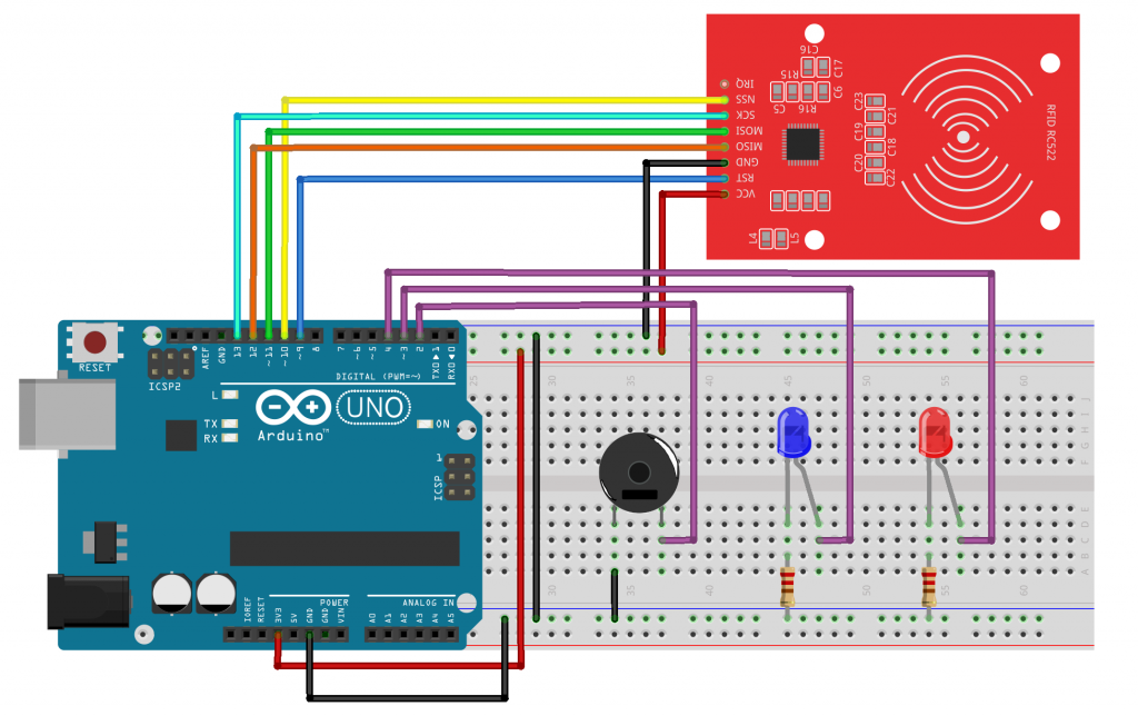
In this tutorial we are going to be exploring the RC522 module and the default Mifare tags that it comes with. The RC522 module may come unsolded so do well to selder the pins so that you can use it on bread boards.
This lesson is quite in depth since you need to really understand certain important things before you can personalize it. So brace yourself and lets do this thing!!!

The Circuitory

Lets begin by setting the RFID enviroment up.

This is the setup we will be using throughout the project.
For visualizations we will use the Serial monitor for simplicity.
Pay attention to the pin connections. The RFID reader will communicate with the Arduino Board using SPI(Serial peripheral interface) that is why you can see the MOSI, MISO, SCK, SDS/SS pins being used.

The RC5522 module pin out

The RCC5522 pin can communicate with the arduino using communication protocols such as SPI, i2C and UART but in this setup we are using the SPI connections.

  • VCC: This should be connected to the 3.3v of your arduino
  • GND: To the ground of your arduino
  • RST: This is the reset pin of the Rc522. When the pin goes LOW, it powers the whole RFID circuitory down and when it comes back high, it starts again at fresh. Connect it to pin 9 of your arduino. It can be connected to any other digital pin though
  • MISO: This is the Master-In-Slave-Out pin. It is one of the neccessary pins to establish an SPI connection. Connect it to pin 12 of Arduino UNO.
  • MOSI: This is the Master-Out-Slave-In pin. It is also one of the neccessary pins to establish an SPI connection. Connect it to pin 11 of arduino UNO.
  • SCK: This is the serial clock pin. It is also neccessary for SPI connection. Connect this to pin 13 of Arduino UNO
  • SS/SDA: This is the Serial data pin. It acts as the signal input pin for the SPI connection.
  • IRQ: This is an interupt pin, It can tell the microcontroller when an RFID tag comes around but we will leave it unconnected for this project.

Establish these simple connections and lets continue

The first codes

The first codes we are going to upload to this setup is going to do something simple. When you bring an RFID tag infront of the RFID reader, it will read all the information on the RFID tag and spit them on the serial monitor. Programming an RFID from scratch is very hectic so we are going to make use of a powerful library that will make things quite simple for us.

Open your libraries manager at Tools>Manage Libraries and search for this MFRC522. Install this particular library!
Next We are going to run one of the examples in the library named “Dump Info”.

What this example does is to scan any RFID tag and spit all the storage layout and all the data  in the RFID tag out unto the Serial monitor. So when you run this code, make sure to also open your serial monitor. Also when you send the card close to the reader, let it finish reading everything before you withdraw it.

Understanding the Layout of the RFID storage.

The layout printed on the screen may look scary at first sight but dont worry its nothing big. Am going to try and break it down as best as possible for you to understand.
What you are seeing printed on the screen is the whole memory space of the Mifare RFID tag. It has a storage capacity of 1kB(1KiloByte). This entire 1KB is what you see on the screen.

  • As you can see, it has been devided into 16 different sectors counting from 0 to 15 from the buttom of the screen.
  • Each sector is also divided into 4 Blocks.
  • Each block can hold 16 bytes of data.

So when you do the math, 16 Sectors x 4 Blocks x 16 Bytes = 1024 Bytes. But 1024Bytes = 1 KiloByte.

If you pick Sector 14 for example it has 4 blocks starting from Block 56 to Block 59. All the blocks can store 16 bytes of data but the topmost block, that is the 4th block of each sector is a special one. They are called Sector Trailers and they contain Access Bits which give Read/Write permissions to the rest of the blocks in the sector. So for every sector you are free to store any other information in the rest of the 3 blocks.

However, Sector 0, which is the first sector of every Mifare RFID tag, has a special case.

In secotor 0, apart from block 3 which contains its Access Bits, Block o is also the manufacturer block containing the Unique Identifier(UID) of the entire Tag.

NOTE: This UID is unique to every card and it also risky to change whatever information stored in there.

Writing to an RFID tag

Now that you are farmiliar with the Mifare tag’s layout, lets try and store our own information on the tag. Remember that, there are some special blocks we dont have to edit though.
In the codes below we are going to write any information of our choice in any of the editable blocks. I chose block 13. Copy these codes and run it. You can change the block you want to write to and you can change the information as well.

#include <SPI.h>      //include the SPI bus library
#include <MFRC522.h>  //include the RFID reader library

#define SS_PIN 10  //slave select pin
#define RST_PIN 5  //reset pin

MFRC522 mfrc522(SS_PIN, RST_PIN);  // instatiate a MFRC522 reader object.
MFRC522::MIFARE_Key key;          //create a MIFARE_Key struct named 'key', which will hold the card information

//this is the block number we will write into and then read.
int block = 13;

byte blockcontent[16] = {"This is Aaenics"};  //an array with 16 bytes to be written into one of the 64 card blocks is defined
//byte blockcontent[16] = {0,0,0,0,0,0,0,0,0,0,0,0,0,0,0,0};  //all zeros. This can be used to delete a block.

//This array is used for reading out a block.
byte readbackblock[18];

void setup() {
  Serial.begin(9600);        // Initialize serial communications with the PC
  SPI.begin();               // Init SPI bus
  mfrc522.PCD_Init();        // Init MFRC522 card (in case you wonder what PCD means: proximity coupling device)
  Serial.println("Bring the card to be written to...");

  // Prepare the security key for the read and write functions.
  for (byte i = 0; i < 6; i++) {
    key.keyByte[i] = 0xFF;  //keyByte is defined in the "MIFARE_Key" 'struct' definition in the .h file of the library
  }
}

void loop()
{
  // Look for new cards
  if ( ! mfrc522.PICC_IsNewCardPresent()) {
    return;
  }

  // Select one of the cards
  if ( ! mfrc522.PICC_ReadCardSerial())
  {
    return;
  }
  Serial.println("card selected");

  //the blockcontent array is written into the card block
  writeBlock(block, blockcontent);

  //read the block back
  readBlock(block, readbackblock);

  //uncomment below line if you want to see the entire 1k memory with the block written into it.
  mfrc522.PICC_DumpToSerial(&(mfrc522.uid));

  //print the block contents
  Serial.print("read block: ");
  for (int j = 0 ; j < 16 ; j++)
  {
    Serial.write (readbackblock[j]);
  }
  Serial.println("");
}


//Write specific block
int writeBlock(int blockNumber, byte arrayAddress[])
{
  //this makes sure that we only write into data blocks. Every 4th block is a trailer block for the access/security info.
  int largestModulo4Number = blockNumber / 4 * 4;
  int trailerBlock = largestModulo4Number + 3; //determine trailer block for the sector
  if (blockNumber > 2 && (blockNumber + 1) % 4 == 0) {
    Serial.print(blockNumber);
    Serial.println("This is a trailer block:");
    return 2;
  }
  Serial.print(blockNumber);
  Serial.println(" This is a data block:");

  //authentication of the desired block for access
  byte status = mfrc522.PCD_Authenticate(MFRC522::PICC_CMD_MF_AUTH_KEY_A, trailerBlock, &key, &(mfrc522.uid));
  if (status != MFRC522::STATUS_OK) {
    Serial.print("PCD_Authenticate() failed: ");
    Serial.println(mfrc522.GetStatusCodeName(status));
    return 3;//return "3" as error message
  }

  //writing the block
  status = mfrc522.MIFARE_Write(blockNumber, arrayAddress, 16);
  //status = mfrc522.MIFARE_Write(9, value1Block, 16);
  if (status != MFRC522::STATUS_OK) {
    Serial.print("MIFARE_Write() failed: ");
    Serial.println(mfrc522.GetStatusCodeName(status));
    return 4;//return "4" as error message
  }
  Serial.println("block written");
}


//Read specific block
int readBlock(int blockNumber, byte arrayAddress[])
{
  int largestModulo4Number = blockNumber / 4 * 4;
  int trailerBlock = largestModulo4Number + 3; //determine trailer block for the sector

  //authentication of the desired block for access
  byte status = mfrc522.PCD_Authenticate(MFRC522::PICC_CMD_MF_AUTH_KEY_A, trailerBlock, &key, &(mfrc522.uid));

  if (status != MFRC522::STATUS_OK) {
    Serial.print("PCD_Authenticate() failed (read): ");
    Serial.println(mfrc522.GetStatusCodeName(status));
    return 3;//return "3" as error message
  }

  //reading a block
  byte buffersize = 18;//we need to define a variable with the read buffer size, since the MIFARE_Read method below needs a pointer to the variable that contains the size...
  status = mfrc522.MIFARE_Read(blockNumber, arrayAddress, &buffersize);//&buffersize is a pointer to the buffersize variable; MIFARE_Read requires a pointer instead of just a number
  if (status != MFRC522::STATUS_OK) {
    Serial.print("MIFARE_read() failed: ");
    Serial.println(mfrc522.GetStatusCodeName(status));
    return 4;//return "4" as error message
  }
  Serial.println("block was read");
} 

Since every block can hold only 16 bytes it means it can hold only 16 characters so be mindful of what you can store in a block.

byte blockcontent[16] = {"This is Aaenics"};  //an array with 16 bytes to be written into one of the 64 card blocks is defined 

If you store something in a block, it is stored as Hexadecimal numbers. But when you decode them they appear as the original words again. You should read about hexadecimal numbers if you do not know them.

So on the left you can see block 13 is now having some hexadecimal values in there, it is the same as “This is Aaenics” which you can change in the codes.

In the next Section of this tutorial we are going to build a simple project where we assign a “Master Key” to a system. The only way someone can get access to the sytem is when the person has a specific RFID tag.

Building an RFID secured system

So we are going to modify the circuit a bit and add a two LEDs of different colors and piezo buzzer. When the user brings the valid RFID tag, a blue LED will blink with a piezo buzzer calmly to indicate “Access Granted” but when the user uses an invalid card, the red LED will blink wih the buzzer harshly to indicate “Access Denied”.
Just this simple right?

So modify your privious circuit as follows. Connect the buzzer and the LEDs to any of your digital pins.

The codes

In the codes below the program has to know the UID of the card you want to allow access to your system even before you run the codes. So make sure to run the previous “Dump Info” codes we run earlier in other to see and copy its UID. With Mifare Tags, only the first 4 bytes of the UID block is enough to be the unique identifier so copy just the first 4 bytes.

#include <SPI.h>
#include <MFRC522.h>

#define RST_PIN 9
#define SS_PIN 10

int buzzer = 2;
int blue_LED = 3;
int red_LED = 4;

byte readCard[4]; //a buffer used to extract the raw UID bytes
String tagID = ""; //This will store the string form of the tag ID extracted

String MasterTag = "E745D619";  // REPLACE this with your Tag ID!!!

MFRC522 mfrc522(SS_PIN, RST_PIN);//Create MFRC522 object

void setup()
{
  // Initiating
  SPI.begin(); // SPI bus
  mfrc522.PCD_Init(); // MFRC522
  Serial.begin(9600);

  pinMode(blue_LED, OUTPUT);
  pinMode(red_LED, OUTPUT);
  pinMode(buzzer, OUTPUT);

  Serial.println("Scan Your Card>>");
}


void loop() {

  //Wait until new tag is available
  while (getID())
  {
    if (tagID == MasterTag) {
      Serial.println(" Access Granted!");

      digitalWrite(blue_LED, HIGH);
      digitalWrite(buzzer, HIGH);
      delay(100);
      digitalWrite(blue_LED, LOW);
      digitalWrite(buzzer, LOW);
      delay(50);

      digitalWrite(blue_LED, HIGH);
      digitalWrite(buzzer, HIGH);
      delay(100);
      digitalWrite(blue_LED, LOW);
      digitalWrite(buzzer, LOW);

    }

    else {
      Serial.println(" Access Denied!");

      for (int i = 0; i <= 5; i++) {
        //this for loop creates a fast blinking led and harsh buzzing sound
        digitalWrite(red_LED, HIGH);
        digitalWrite(buzzer, HIGH);
        delay(100);
        digitalWrite(red_LED, LOW);
        digitalWrite(buzzer, LOW);
        delay(50);
      }
    }

    Serial.print(" Your Tag's ID : ");
    Serial.println(tagID);
    delay(500);
    Serial.println(" ");
    Serial.println("Scan Your Card>>");
  }

}

//Read new tag if available
boolean getID()
{
  // Getting ready for Reading PICCs
  if ( ! mfrc522.PICC_IsNewCardPresent()) { //Check if there is a new card
    return false;
  }
  if ( ! mfrc522.PICC_ReadCardSerial()) { //check if the card can be read
    return false;
  }
  tagID = "";
  for ( uint8_t i = 0; i < 4; i++) {
    //for the MIFARE tag we can extract only the first 4 bytes of the uid block as its UID
    //readCard[i] = mfrc522.uid.uidByte[i];
    tagID.concat(String(mfrc522.uid.uidByte[i], HEX)); // complies all the 4 bytes into a string
  }

  tagID.toUpperCase(); //makes sure all letters are in uppercase.
  mfrc522.PICC_HaltA(); // Stop reading
  return true;
} 

The only new thing in these codes is the new getID() function created below the void loop() function. This getID() function does a simple job; it is the one responsible to check if there is any RFID card presesnt. If a card is present it will extract the first 4 bytes of the uid block, convert it into a string and store it in the tagID variable which is later used for the comparison in the void loop() function.

After uploading it you can test other cards apart from the one you assigned and see the effect. The blue key holder in the RFID set is also an RFID tag so dont forget to test that one too.

Related Articles

Using the dual axis analog joystick module

Where are the game center squad?
Do you remember those guys behind the UCOM game pad who would be like “oh as for me I play FIFA well with analog” and at the end of the day they would still loose the match, eiiiii?
You know what, today we will be doing something more technical and fantastic with one of the joystick modules.
We will learn how to harvest the x and y coordinates out of the joystick and use it to control things in real life…..

Addressing the Newbie Passions!

Since the days the worlds were formed by the Great I Am, humanity has never stopped expressing the creative power that was embeded in us since day 1! From before the agricultural age through the 1st industrial revolution to the 4th revolution on whose gates I stand and write today, there has always been the need to invent new things or make a way of life better than a previous.

The 555 timer IC.

As a hobbyist, engineer, or maybe an electronics geek or wherever you find yourself, you can’t really have the time and pleasure to know what goes on in all the million ICs in the world. However you can delve with me into this simple 555 timer to see whats going on in it. This can give you a certain level of understanding about almost all ICs.

Responses

Your email address will not be published. Required fields are marked *