
Potentiometer Controlled LED
In the “toggle an LED” article you realize that your circuit had only two distinct events, a HIGH (1) thus “ON” and a LOW (0) thus “off”. Your LED could only be off or on at a moment. That LED was strictly operated under digital conditions of 1 and 0. But in some cases in real world, you’d love to control the brightness of your LED. You’d love to rather make your LED dim than completely switching it off and this is where Analog signals come into play. If you have a voltage source of say 9V, an analog circuit can someway divide the 9V into discrete or calibrated voltages to control the voltage drop across whatever load you have in your circuit. At a particular time you can make the voltage across the load be anywhere between “0volts” to “9volts”. So yes it’s possible to have 3.2 volts across your load and when you feel like increasing it you can increase it to 4.8V or reduce it 1.4V at any time.
Details about how this is achieved is explained with the voltage division circuit in “how the potentiometer works”.
In this project we are going to learn how to control the brightness of an LED with the use of a Potentiometer.
So note this, whenever you hear about “controlling brightness, controlling speed, controlling loudness” etc. know that it’s not a digital signal at play but analog signals….
This is a picture of a common potentiometer you will find in electronics kits and can easily get in stores.  It is a 3 pin components that works as a variable resistor. The middle pin is the output pin that goes to the load to be controlled, in our case here, the anode of the LED.
Note that the LED is a diode and allows current to pass through it in one direction.
The other two pins on the left and right of the potentiometer are the input pins. It takes the highest voltage at one pin and takes the lowest voltage at the other pin. It is these two input signals that are being compared and outputted at the output (middle pin) when the nob of the potentiometer is rotated every time.
Get ready to build now;
- A bread board

- A few jumper wires

- Your voltage source

- An LED of choice

- A potentiometer
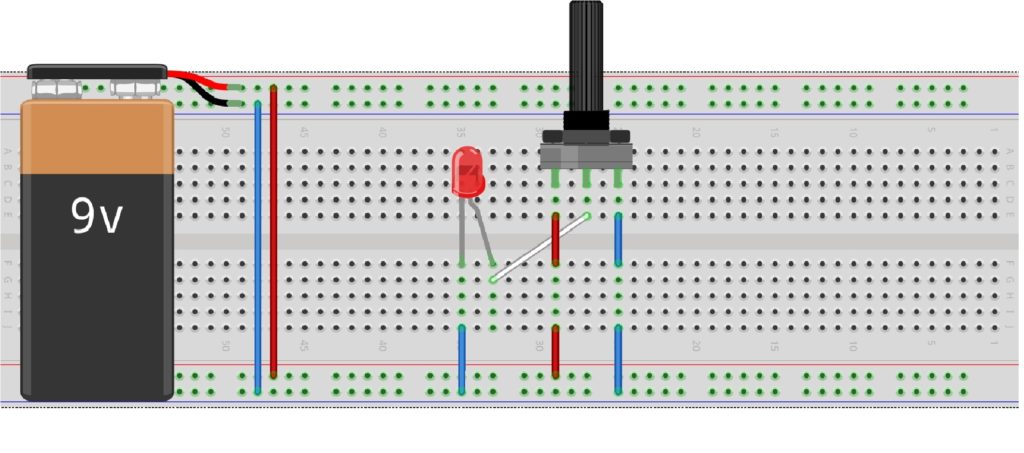
With your bread board in place, connect your voltage source to any of the power rails.
Now connect the positive of your voltage source to one end of the  potentiometer and connect the negative to the other end of the potentiometer.
The potentiometer is still a resistor and not a diode so the positive and negative can be swapped. The only difference between the two configurations is the behavior of the LED when the nob is rotated clockwise or anticlockwise.
With the input signals connected to the potentiometer successfully, get your LED in place and connect the output pin (thus the middle pin) of the potentiometer to the anode of the LED.
Now ground your LED by connecting its cathode to the negative of your power source. Your circuit should be working perfectly if you have no bugs in there.
Rotate the nob of the potentiometer to see how the LED is affected.
In other not to get your LED fried you have to cater for the maximum voltage that reaches your LED. The potentiometer, when rotated to brighten the LED can allow the full source voltage to go across the LED. And in the diagram above, the source voltage is 9volts and that’s too big for the LED.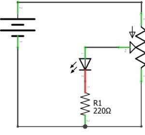
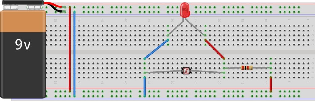
The solution to this is very simple. Before you ground the LED by connecting its cathode to the negative of your source voltage, connect a series resistor it. 220 ohms will work perfect.


Responses