• Home
  • Aaenics Store
  • Aaenics community
  • AaenoTutor
  • Explore
  • About

    Shopping Cart

    No products in the basket.

    Sign in Sign up

    Shopping Cart

    No products in the basket.

    • Home
    • Aaenics Store
    • Aaenics community
    • AaenoTutor
    • Explore
    • About

    Category: Basic circuitory

    How to build an Inverting Operational Amplifier

    Welcome to another exciting Tutorial from Aaenics. Still on the linear electronics series and if you’ve been following for a couple of weeks now you’ll…

    Kwaku Effa 15th October 2019
    0 Comments

    Your Op-amp needs this power supply circuit

    Hei there, welcome to another tutorial from Aaenics. Today we want to learn something special when it comes to working with Operational amplifiers. Its more…

    Kwaku Effa 25th September 2019
    0 Comments

    Introductioin to Operational Amplifiers

    If you are reading this article then at least you are aware that computers and electronics devices reason, trade, communicate, take decisions or generally operate…

    kwaku 13th September 2019
    0 Comments

    The Astable mode of the 555 timer

    From my previous post about the 555 timer, I made it clear that the 555 timer can be used to build 3 different kind of…

    kwaku 25th June 2019
    0 Comments

    Blink an LED with the 555 timer

    Overview of project Materials and components needed Step by Step Tutor Overview of project In this project we are going to build a circuit with…

    Kwaku Effa 25th June 2019
    1 Comment

    The 555 timer IC.

    As a hobbyist, engineer, or maybe an electronics geek or wherever you find yourself, you can't really have the time and pleasure to know what goes on …
    kwaku 17th June 2019
    0 Comments

    Starting up with Integrated circuits

    A little history Like all other things, Integrated circuits also have a history, they didn’t just appear and are all over the place all of…

    Kwaku Effa 4th June 2019
    1 Comment

    Hacking the joystick Module

    Just Imagine you create a robot or a machine or a crane which you want it to lift objects and put them at another place…

    Kwaku Effa 16th April 2019
    2 Comments

    Digital and Analog Command circuits

    In this post I am attempting to give an overview of two main and very important things you should know when it comes to electronics,…

    Kwaku Effa 25th March 2019
    0 Comments

    Do some magic with the LDR

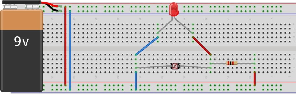
    Overview Materials needed Set up Overview What you need to know; Ohms law. Voltage division. How to use the breadboard. How the LDR works. In…

    Kwaku Effa 8th March 2019
    0 Comments
    Load More

    Basket

    Categories

    Recent Posts

    • Aaenics – Nvidia AI Emerging chapters
    • Understanding RFIDs and Integrating them in your projects
    • Introduction to NRF-24 Radio Transceiver
    • Digitize Your Soil With A Sensor
    • Using the dual axis analog joystick module
    The Multifaceted Tech and Robotics Wheel for the Race
    © 2023 - Built at Aaenics_labs

    Forum Description

    Overview Materials needed Set up Overview What you need to know;
    • Ohms law.
    • Voltage division.
    • How to use the breadboard.
    • How the LDR works.
    In this piece, we are going to build a practical circuit with the Light Dependent Resistor. Recalling, the LDR, we know its resistance, is dependent on the intensity of light incident on it. It has a very high resistance when there is NO or LOW light incident on it and it has low resistance when more light is incident on it. It is this property of it which we are going to harness to create something magical for ourselves. So we are going to build a simple light sensing system which is going to read our environment’s light intensity and later Toggle an LED high or low depending on the light intensity of the surrounding. But just the LDR cant do this magic, we are also going to harness a marvelous behavior of the voltage division to create something spectacular.

    Why voltage division?

    When you have a voltage divider circuit consisting of just two resistors of the same value like in the schematic on the right, we know that both resistors will have the same voltage drop across them. True or not true?But we also realize that, if the resistors are of different resistances, there will  be surely more voltage drop across the big resistor than the small. That’s very true and can be proven by ohm’s law: V=IR. Now see this, if the value of one of the resistors is kept constant and the other is varied such that at a point in time, it has more resistance than the fixed resistor and another time it has less resistance than the fixed resistor, you will also find out that the voltage drop across them will be changing as their resistances change. The only property that remains constant is the fact that, “at any time ‘t’ the resistor with the highest resistance has more voltage drop across it. “ And it is this property that we need. Now lets put the pieces together to make some sense. The LDR is going to be our variable resistor, such that, when there is low or no light, it will have more resistance, and hence more voltage drop across it than the fixed resistor. And when there is enough light on it, it will have less resistance and less voltage drop across it. 

     The objective Logic.

    The logic we want to have at the end of the day is this;when there is no light——-we want to command an LED to come alive. (HIGH).A question to ask yourself now is,  when there is no or low light, which resistor has more voltage drop across it? surely the LDR. And so we are going to connect our load (the LED) across the LDR, thus in parallel with the LDR. So the fate of the LED will always be decided by the LDR.  And on the other side,  when there is enough light, the LDR will decrease in resistance and hence decrease in voltage. Now if the voltage drop across the LDR is too small the LED will also not get the required voltage to stay on and will surely go off. Lets move on to build it real to understand more. Materials needed
    • A bread board
    • A few jumper wires
    • Your voltage source
    • An LED of choice
    • An LDR
    Set up As usual, get your bread board in place with your voltage source connected to the power rails.
    • Firstly, construct a voltage divider circuit with your LDR and the fixed resistor as in the schematics.
    •  One leg of the fixed resistor goes to positive of the voltage source and the other leg connects to the LDR.
    •  The other leg of the LDR is then grounded to make a complete loop.
    Your voltage divider is ready!
    • So as we learnt earlier on, the LDR will have more voltage dropped across it when it is dark. Hence when it is dark and we want an LED to be lit, that LED will have to tap its voltage source from the LDR.
    • Connect your LED in parallel to the LDR and see the magic.

    The value of the fixed resistor

    Depending on the environment you find yourself in and also depending on how sensitive you want your system to be to light, the value of the fixed resistor may change. But you can find a suitable value by using an approach am going to explain here:  Lets take just one condition, thus, at night.
    • The first assumption is, at night, the LDR will reach its maximum resistance, let that resistance be “y”. Most LDRs can reach 1Megaohm.
    • If your source voltage is 9V, then about 8V will be across your LED at this time. And hence 1V across the fixed resistor. Let the value of the fixed resistor be “x”.
    • From the voltage divider rule you can calculate for the value of “x” in 1=9x/(x+y). where “1” is the voltage drop across the resistor during the night condition and “9” is the value of your voltage source.
    Olalaa have some fun with the circuit!

    As we begin to Assemble, lets know we are in a Beta Mode. But lets not forget, egobe! Dismiss

    Report

    There was a problem reporting this post.

    Harassment or bullying behavior
    Contains mature or sensitive content
    Contains misleading or false information
    Contains abusive or derogatory content
    Contains spam, fake content or potential malware

    Block Member?

    Please confirm you want to block this member.

    You will no longer be able to:

    • See blocked member's posts
    • Mention this member in posts
    • Invite this member to groups
    • Message this member
    • Add this member as a connection

    Please note: This action will also remove this member from your connections and send a report to the site admin. Please allow a few minutes for this process to complete.

    Report

    You have already reported this .
    • About WordPress
      • WordPress.org
      • Documentation
      • Support
      • Feedback
    • Log In
    • Register