Blink an LED with the 555 timer

In this project we are going to build a circuit with the 555 timer in the Astable mode. And we are simply going to make an LED blink continuosly at a speed which we can troll.
From the previous page, more has been said about the 555 timer and its capabilities in its Astable mode. However, one other thing we should know is this.
1) The components that determine the frequency of the oscillation: in the schematics you will see two resistors labelled R1 and R2 and you’ll also see another capacitor labelled C1. It is the values of these Resistors and capacitor that determines the nature of your output. Feel free to change the values to see what happens with your circuit.
know these terms too.
High Time: It is the time in seconds the LED will spend being on or at Logic 1(HIGH). And the formulae for this time is 0.693 x C1 x (R1 +R2)
Low Time: it is the time in seconds the LED will spend being off or at logic 0(LOW). And the formulae for this time is 0.693 x C1 x R1
So for example if you use two 100K resistors for R1 and R2 and use a 10uF capacitor for C1 your circuit will have a high time of 1.386 seconds and a low time of 0.693 seconds.
GO to the next tab and lets build something!
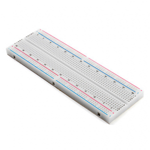
- A bread board

- Jumper wires

- Two 100k ohm Resistors (You can choose any other two depending on the HIGH and lOW times you want

- Power source

- An LED of your Choice

- A 10uF capacitor (choose any value depending on the HIGH and LOW times you want)

- And an NE555 IC

- Get your bread board in place
- Connect your voltage source to the power rails
- Fix the 555 IC in the Ravine of the bread.

- Follow the Schematics closely and by means of jumper wires, join each of the 8 pins to the various places.
- pin 1 goes to ground(GND)
- pin 8 goes to VCC.
- connect pin 2 to pin 6
- pin 4 is the Reset pin. It is active low so always connect it to VCC when you don’t need to reset anything.
- connect R1 from pin 7 to pin vcc.
- connect R2 from pin 6 to 7.
- Capacitor C1 also connects from pin 6 to the ground
- (Remember that R1, R2 and C1 are what will determine the nature of your output at pin 3)
- Pin 5, is which is the control pin is nt needed in this application but it is mostly connected to ground through a very small capacitor like the 10nF to prevent electrical noises
- pin 3 is the OUTPUT pin, connect it to the anode of your LED.
- Connect the cathode of the LED to ground through a limiting resistor, 220ohm will do.
- Yaay! your circuit should be on autopilot by now! Watch the video above the post to also see the circuit being built.


Responses