• Home
  • Aaenics Store
  • Aaenics community
  • AaenoTutor
  • Explore
  • About

    Shopping Cart

    No products in the basket.

    Sign in Sign up

    Shopping Cart

    No products in the basket.

    • Home
    • Aaenics Store
    • Aaenics community
    • AaenoTutor
    • Explore
    • About

    Author: Kwaku Effa

    Aaenics – Nvidia AI Emerging chapters

    Loading…

    Kwaku Effa 24th June 2021
    0 Comments

    Understanding RFIDs and Integrating them in your projects

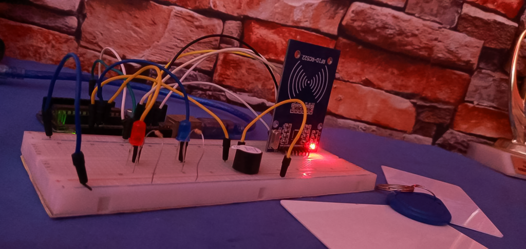
    The first time I saw an RFID card, my team and I were representing Ghana at the World Robot Olympiad. We lodged in a beautiful…

    Kwaku Effa 6th January 2021
    0 Comments

    Using the dual axis analog joystick module

    Where are the game center squad? Do you remember those guys behind the UCOM game pad who would be like “oh as for me I play FIFA well with analog 
    Kwaku Effa 7th September 2020
    0 Comments

    Extracting the raw sound waves

    Did you know that humans have a hearing range between 20Hz and 20kHz? and even the fact that as we grow older our hearing becomes…

    Kwaku Effa 18th August 2020
    2 Comments

    Using the Digital Humidity and temperature sensor

    Of the many sensors you will find yourself using, the DHT sensors are quite complicated. Retrieving data from this sensor is not as simple as it is fo…
    Kwaku Effa 26th July 2020
    1 Comment

    Addressing the Newbie Passions!

    Since the days the worlds were formed by the Great I Am, humanity has never stopped expressing the creative power that was embeded in us since day 1! …
    Kwaku Effa 16th July 2020
    9 Comments

    Using an Infrared Proximity sensor.

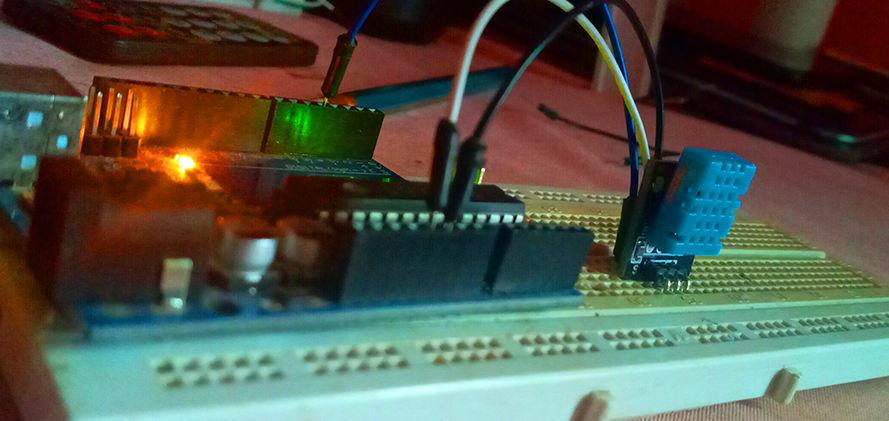
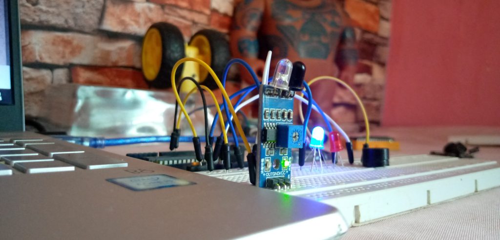
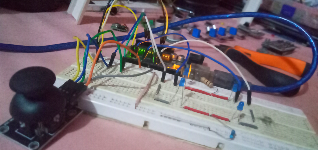
    There are so many sensors out there today because of the fact that we want our robots, machines and systems we design to have some…

    Kwaku Effa 18th April 2020
    3 Comments

    Controlling the speed and direction of a DC motor.

    https://youtu.be/Cp_SK3HS1HI Dc motors were one of the coolest things most of us used to play with as kids. You should even recognize this particular one…

    Kwaku Effa 11th April 2020
    3 Comments

    Motion detection with the PIR motion sensor.

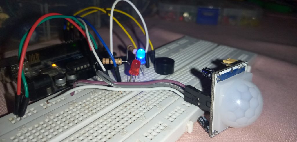
    Why at all would you need to detect motion? And why is the PIR motion sensor a good option? Okay welcome to another quick and…

    Kwaku Effa 4th April 2020
    8 Comments

    How to build an Inverting Operational Amplifier

    Welcome to another exciting Tutorial from Aaenics. Still on the linear electronics series and if you’ve been following for a couple of weeks now you’ll…

    Kwaku Effa 15th October 2019
    0 Comments
    Load More

    Basket

    Categories

    Recent Posts

    • Aaenics – Nvidia AI Emerging chapters
    • Understanding RFIDs and Integrating them in your projects
    • Introduction to NRF-24 Radio Transceiver
    • Digitize Your Soil With A Sensor
    • Using the dual axis analog joystick module
    The Multifaceted Tech and Robotics Wheel for the Race
    © 2023 - Built at Aaenics_labs

    Forum Description

    Welcome to another exciting Tutorial from Aaenics. Still on the linear electronics series and if you've been following for a couple of weeks now you'll know we've being playing around the operational amplifier, the LM358 dual op-amp to be specific. Today in this wonderful tutorial, we will learn briefly what an inverting op-amp is, and how to actually build one for your self .

    What is an Inverting Operational Amplifier?

    An inverting Operational Amplifier circuit like any other op-amp circuit can or will take a small signal you input, amplify it and then give you a larger output. The special thing here is that, the output signal of the inverting amp will be out of phase with the input signal. Maybe you will be asking what it means for one signal to be out of phase with the other, what this means in simple English is that, one signal at a particular time will be completely opposite in direction to the other signal. So for example, if my input is 0.3V DC, and my inverting amplifier has a gain of x(-10), my output will be -3V, which you can see that though it has been amplified ten times, it is opposite in polarity to the original 0.3V. So the work of the inverting amp here is to amplify and give me the opposite polarity of my input. As simple as that. Also if the input signal was to be -0.3v, the amp would have given out 3V. Okay so from here we are going to build an inverting amp circuit that will give us a practical understanding of inverting amp circuits. Schematics This is a schematic diagram of what is to be built. This is also a virtual breadboard view of the circuit. Materials Needed The first part of the circuit is simply a dual power supply which we learnt how to build in the previous tutorial, you will need it to power your op-amp. Here is what you need to build it.
    • Power Supply, preferably a 9v battery.
    • 2 Resstors of the same value.
    • Two capcitors of the same value.
    • A few jumper wires.
    The Above components will be used to build the dual polarity power supply for the op-amp ic. The rest below is needed to build the inverting amp it self.
    • 1 potentiometer
    • The op-amp Ic to be used. The LM358 dual op-amp is used in our case.
    • Select 2 LEDs of different colors
    • Two 220ohm resistore for Rf and Rin
    Steps
    • Okay so we are going to build an inverting operational amplifier circuit. Inverting amps are used in a whole lot of applications or specific projects but in this tutorial we are aiming at building a general response inverting amp circuit that will toggle two different LEDs  depending on the kind of output signal we get.
    • From the schematics, you can see LED1(green) and LED2(red) are connected in parallel but opposite to the other. One end of the Parallel structure is connected to the output(PIN 1) of the LM358 IC. and the other end of the two LEDs is connected to ground(0 volts) through a series resistor.
    • The non inverting Input(that is pin 3) of the IC is also connected to ground(0 volts). Note that the ground(0 volts) is in the middle  of the voltage divider of the power supply.
    • Since no feed back resistor is used in this circuit, the gain of the amplifier is infinity.
    • A potentiometer takes input from the +vcc and –vcc of the supply and its middle pin is connected to the input of the op-amp. It is this potentiometer that will control or vary the input signal.
    • After establishing all connections you will realize that, when the potentiometer is tuned to one end (let say the positive), the op-amp’s output will be negative, hence turning on the reverse biased LED while the forward biased one remains constant. The opposite will happen when the potentiometer is turned to the other end(the negative end.) When it is turned to the negative end, the op-amp’s output will be positive and hence the forward biased resistor will come on while the other is turned of.

    As we begin to Assemble, lets know we are in a Beta Mode. But lets not forget, egobe! Dismiss

    Report

    There was a problem reporting this post.

    Harassment or bullying behavior
    Contains mature or sensitive content
    Contains misleading or false information
    Contains abusive or derogatory content
    Contains spam, fake content or potential malware

    Block Member?

    Please confirm you want to block this member.

    You will no longer be able to:

    • See blocked member's posts
    • Mention this member in posts
    • Invite this member to groups
    • Message this member
    • Add this member as a connection

    Please note: This action will also remove this member from your connections and send a report to the site admin. Please allow a few minutes for this process to complete.

    Report

    You have already reported this .
    • About WordPress
      • WordPress.org
      • Documentation
      • Support
      • Feedback
    • Log In
    • Register