Using an Infrared Proximity sensor.

There are so many sensors out there today because of the fact that we want our robots, machines and systems we design to have some kind of interactions with the enviroment just like we humans do and even more. Proximity is a good topic to consider when it comes to machine interactions. A machine would also want to know if there is any obstacle or object near it so that it can know what to do next.

What is proximity?

Proximity is the measure of the nearness of something. Since it would be very good if our machines and robots also knew how close or far they are to objects in the surroundings, there are many sensors that help them to measure proximity. Some examples are: Radaar sensors, ultrasonic sensors, sonar sensors and many more.
However in this tutorial we are looking at a very common one, the Infared proximity sensor.

Infared proximity Sensors

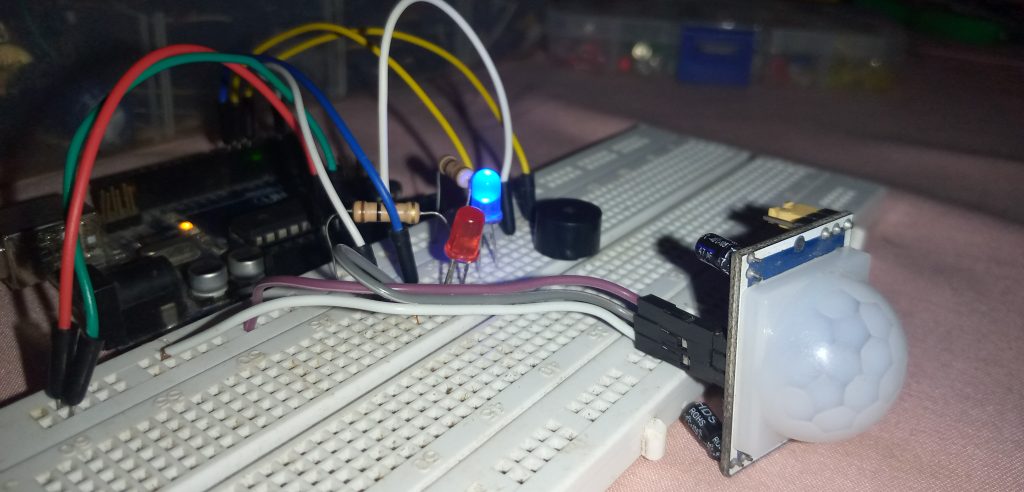
An IR proximity sensor is a sensor that uses Infrared signals to detect the nearness of obstacles. In one of my previous tutorials where I talked about the PIR motion sensors we realized that even though it is an Infrared sensor, it was a passive one! But in the case of the IR proximity sensor it is an active one and i will explain that shortly in the mode of operation.

Mode of operation of IR proximity sensors

The reason why an IR proximity sensors is recognised as active sensors is because of its mode of operation. Unlike the PIR, it emits some amount of IR signals into the enviroment. Incase there is an object, this emitted IR rays will bounce back to the sensor and the sensor will judge by comparing the difference between the two signals(the sent and the received).
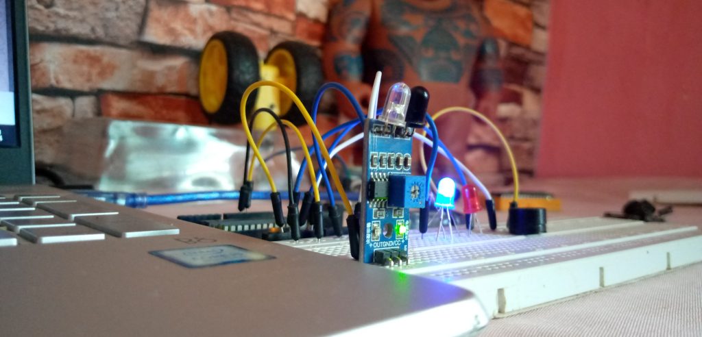
So in this particular IR module which is common to the maker community, there are two key components on the board, 

  • The IR LED
  • The IR receiver
The signal is sent through the IR LED and then when it hits an obstacle it bounces back and it is read by the IR receiver.
 It is important to understand that the IR proximity sensor does not tell you the distance the obstacle is to the sensor. The only thing it can do is to confirm or deny the prescence of an obstacle. Don’t also get confused, it doesn’t also sense movements unlike the PIR does.
The blue potentiometer on it is used to regulate the sensitivity of the sensor.

Hooking up the IR proximity sensor

The sensor has only 3 pins to worry about and they are mostly inscribed on the pcb.

  • VCC
  • GND
  • OUT
The output pin is a straight digital pin. It returns 1 when there is no obstacle detected and it returns 0 when there is an obstacle. Hence it is to be conneccted to digital pins of the microcontroller, which is an arduino in our case today. But note that you can use it in your own customized circuits even without a microcontroller. 


Sample circuit with the fc-51 IR proximity module

In the simple setup above we want to use the Arduino to retrieve the data out of the sensor. And the logic here is this:

If the sensor detects any obstacle, the red LED should come on and also the piezo alarm should sound!
But if there is no obstacle, the blue LED should stay alive.
There are so many applications of this and I cant wait to see you use it in your projects. The basic codes for the project is also below. copy and upload to your arduino IDE, understand it and feel free to edit it to suit whatever project you wish. 
If you need any help too or have some suggestions, the big comment box down there is for you!

And yh you can also share your projects with the whole community.

Codes for the setup


int ir = 2;
int blue = 3;
int red = 4;
int buzzer = 6;
int irstate;

void setup() {
pinMode(ir, INPUT);
pinMode(red, OUTPUT);
pinMode(blue, OUTPUT);
pinMode(buzzer, OUTPUT);
Serial.begin(9600);
}

void loop() {
irstate = digitalRead(ir);
Serial.println(irstate);
if (irstate == HIGH) {
digitalWrite(blue, HIGH);
digitalWrite(red, LOW);
digitalWrite(buzzer, LOW);
}
else if (irstate == LOW) {
digitalWrite(red, HIGH);
digitalWrite(blue, LOW);
while (irstate == LOW) {
irstate = digitalRead(ir);
analogWrite(buzzer, 200);
delay(100);
analogWrite(buzzer, LOW);
delay(100);
}
}

}
 

Related Articles

Using the dual axis analog joystick module

Where are the game center squad?
Do you remember those guys behind the UCOM game pad who would be like “oh as for me I play FIFA well with analog” and at the end of the day they would still loose the match, eiiiii?
You know what, today we will be doing something more technical and fantastic with one of the joystick modules.
We will learn how to harvest the x and y coordinates out of the joystick and use it to control things in real life…..

Responses

Your email address will not be published. Required fields are marked *