
Hacking the joystick Module

Just Imagine you create a robot or a machine or a crane which you want it to lift objects and put them at another place at your command, or you want to control a car with this wonderful joystick module. At the end of the day you will be controlling something in the physical world like you do virtually in video games like need for speed, Road rush and the others. Its going to be amazing yh! But how do we go about it?
A microcontroller like the Arduino was the first and easiest option that came to my mind. The new problem was not how to connect such an input device to the Arduino but rather “which command on the joystick corresponds to which of the wires”.
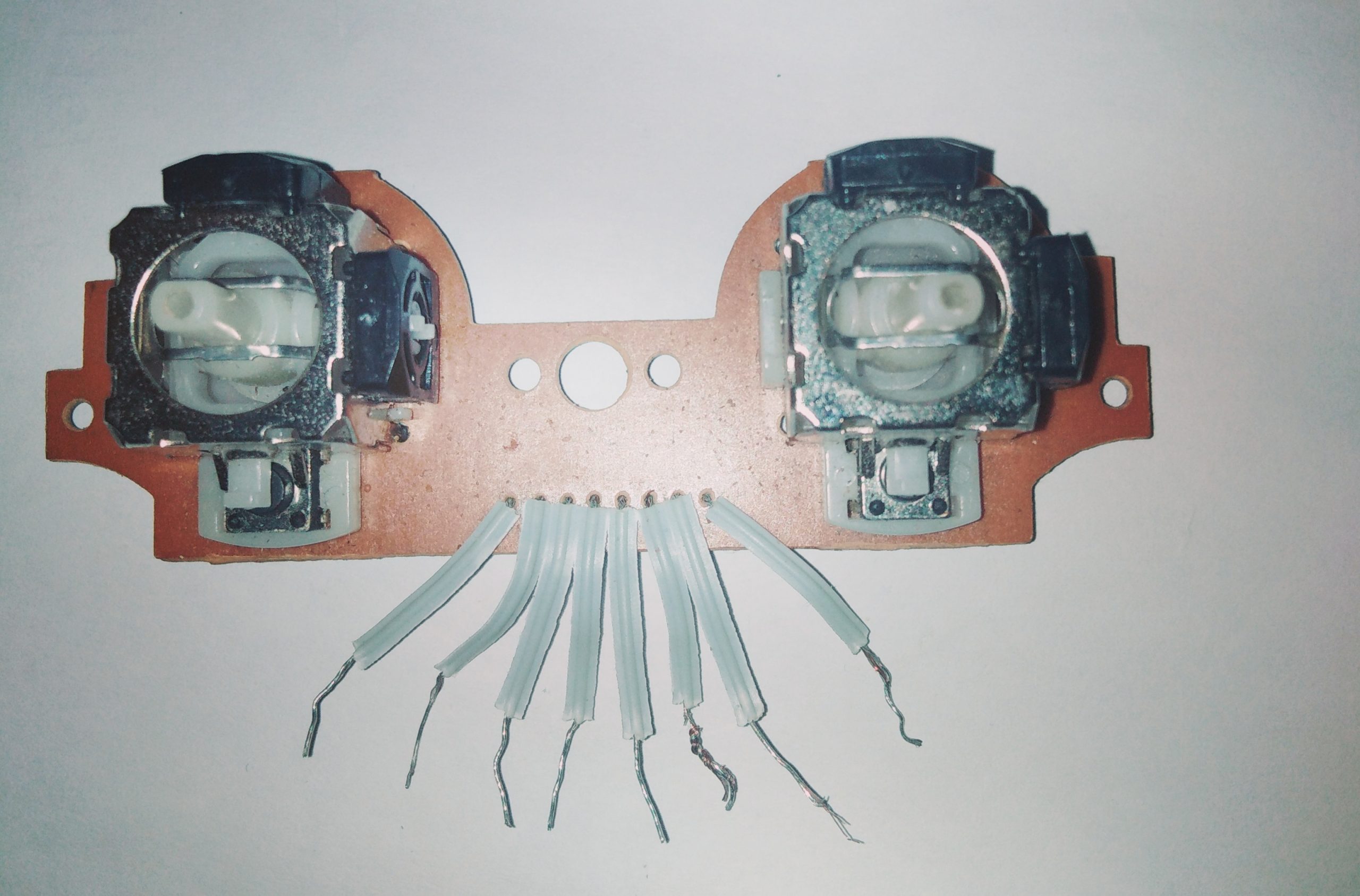
The First thing I had to look for was the VCC and GND. A hint for finding these two was the fact that “they are common to every command and will run throughout the whole circuit”. It was kinda tedious but at the end of the day I succeeded mapping each command to the corresponding pin out.

What are the pin-outs?
At least we know every similar joystick module pair has two push buttons, one on the left joystick and the other on the right joystick. It also has 2 analog controls one on the left and the other on the right. Each Analog control is made up of two “potentiometerlike” components, one lying on the x-axis and the other lying on the y-axis.
So in summary the 8 wires coming from the module are:
- left push button(-digital pin-)
- right push button(-digital pin-)
- left y axis(-analog pin-)
- left x axis(-analog pin-)
- right y axis(-analog pin-)
- right x axis(-analog pin-)
- VCC(goes to 5v of microcontroller)
- GND(goes to ground or 0v of microcontroller)
The above is in no particular other. Depending on the manufacture the positions will vary from one board to the other.
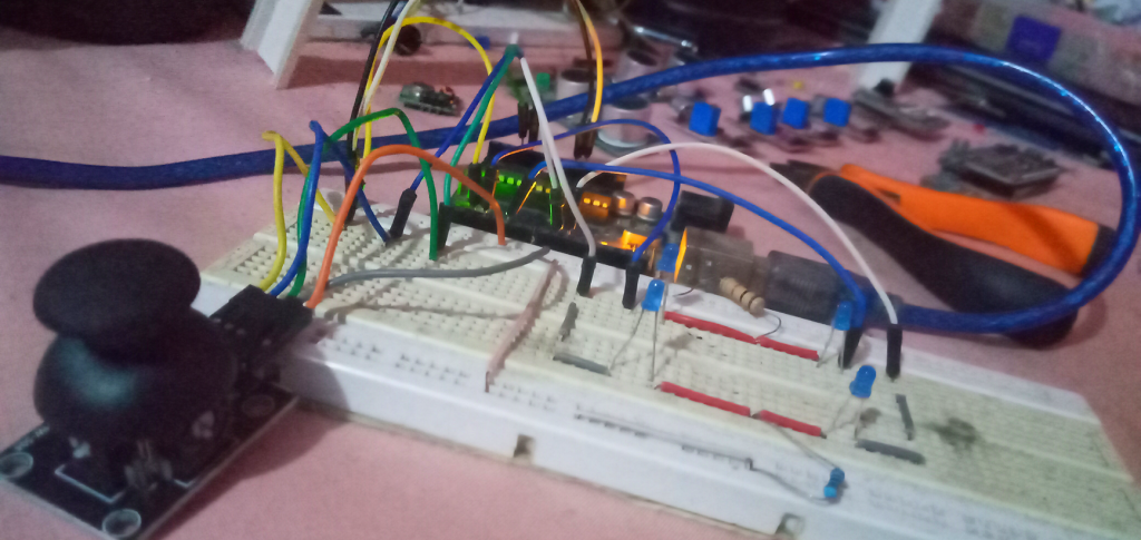
With the help of a microcontroller like the Arduino UNO you can connect the module to appropriate pins of the Arduino and verify if your mappings were all right.


Woooow
Nice introduction,
Since this part introduced us to the pinOut of our joyStick
I would be happy if the second part of this tutorial would be based on interfacing our joyStick to be able to control our Arduino based cars so we could play Need For Speed and Road Rush in real world
thanks 🙂
Hahaa wow you have a really dope idea. I think We should work on that.
Catch me in my dm and lets see.😅