
Digital and Analog Command circuits

In this post I am attempting to give an overview of two main and very important things you should know when it comes to electronics, thus, digital and analog signals. At the end you will understand how to build simple command circuits with either or both types of signals.
In electronics, signals are the means of communication within a circuit or between distinct circuits. These signals may be change in voltages, current, magnetic fields etc. Take this example. A big road separates you and a friend-Your friend sees you and wants to draw your attention-Your friend lifts up his/her hand and gives you a big wave. Yh, in electronics, we would say, your friend has signaled you. We signal people in many other ways too. You can wink at someone when they are close, you can tickle someone, you can talk, you can clap,etc. So basically every signal has a reason to be use at a particular time depending on what you want to archieve.
Lets first explain what these analog and digital signals are.
Digital Signals
Digital signal are also known as binary signals. We know binaries to be either 1s or 0s. This means that digital signals have only two events, they don’t change over over a range of values with respect to time, rather, at any point in time, a digital signal is either 0 or 1. Computer language is all built on 1s and 0s.
What do these two events of 1s and 0s mean to us? For a standard logic in electronics, 1 means ON or HIGH and 0 means OFF or LOW.
An everyday example is the light in your room. The bulb take’s commands from the switch so the switch has to always give the signal for the bulb to react to it. This signal which the switch on the wall gives is obviously a digital signal since it has only two events. It either signals the bulb to come alive or signals it to go off. It cant control the brightness of the bulb. That’s basically how digital signals look like.
Analog Signals
Analog signals on the other side are signals whose values change over a range. This means that analog signals have more events than digital signals. This suggests that analog signals can do more than just turning a bulb on or off but can go on to control how dim or bright the bulb can be at a particular time. Within a range of say 0 to 9 volts, a digital signal can either be at 0 volts or 9 volts but for an analog signal it can be any where between 0-9. eg: 3.2volts.
A common example of an analog signal in operation is how your ceiling fans work. Unlike your bulb that is supposed to be on or off, your fan’s speed has to be controlled. When you build a robot and at a particular point in time you want to control the speed of the motors that control the wheels, remember to use analog commands. with a 9 volts source, 0 volts will mean OFF, 2 volts will put your load ON but dim or slow(LED or motor), 5.6 volts will make it brighter or faster and 9 volts will give you the maximum output.
Signal Generators/commanders
In terms of Input and output, a command circuit which this article addresses is aimed at developing a circuit which receives commands(input signals). So we are going to build two circuits, one that receives digital signals to do something and one that receives analog signals to do something.
What are some examples of input devices and electronic components we can use to give commands to our circuit? All sensors are input components and they may either digital or analog. Push buttons are digital inputs, and a potentiometer can be used as an analog input.
Lets first build a digital command circuit.
Digital Command circuit
In this circuit a push button is used as our digital signal generator(input component) and its going to toggle an LED HIGH when it is at LOGIC 1 and toggle it LOW when it is at LOGIC 0.
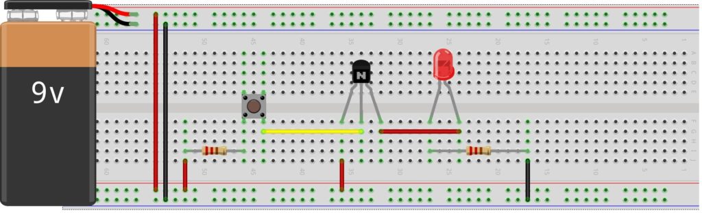

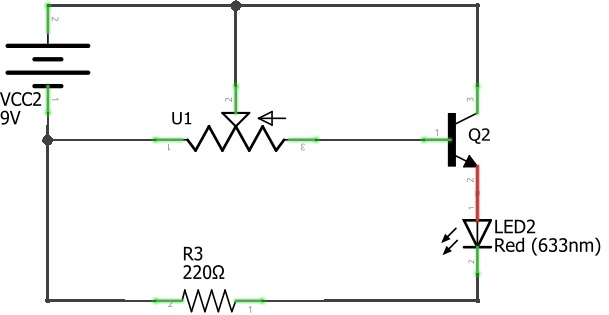
Analog Command Circuit
In this circuit a potentiometer is used as our analog signal generator(input component) and its going to regulate the brightness of an LED by comparing and selecting any value between 0 and the maximum value of our voltage source(9V).


Responses