Extracting the raw sound waves

Did you know that humans have a hearing range between 20Hz and 20kHz? and even the fact that as we grow older our hearing becomes weaker and we begin to loose the ability to hear higher frequencies?
Well, when it comes to the technicalites of sound waves there is so much to it than just frequencies and loudness. Audio signal processing is a really big and interesting thing to delve in.
 In this piece we are going to use a sound sensor to retrieve some raw sound waves with the help of an Arduino UNO, and we’ll build a simple loudness meter with the data we get.

Sound waves

Sound waves are actually longitudenal waves, but most of the time we prefer to represent them as transverse waves for easy understanding and analysis. With every transverse wave we have properties like:

  • Amplitude
  • Wavelength
  • Period
  • Frequency
  • Velocity or speed
Dont worry if you know nothing about these yet. In this tutorial the data that will be extarcted from the sound sensor will be ploted on a live graph for you to see.
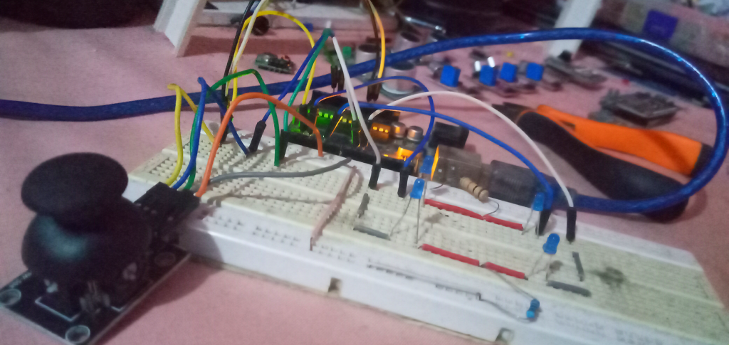
Lets get the KY-038 sound sensor circuit ready for extraction.

The Ky-038 sound sensor module

This is the sound sensor module we are using here. It comprises of a microphone and a simple processing circuit that helps us to retrieve both analog and digital readings from the microphone. We will be making use of the Analog pin rather than the digital pin in this tutorial. You can grab one of these sensors from the Aaenics Store.

Note that the sensitivity of the sensor is adjusted by tuning the potentiometer on it. 

The Circuit

So as you can see, you should be able to set this up in less than 5 mins. The important things to know is that:

  •  You need to conect the Analog output of the sensor to any of the analog pins on your arduino board.
  • You need to power it with 5v for effectiveness.
  • And the RGB anodes of your 3 in one LED shoud also be connected to different digital pins. 
  • You can also use seperate LEDs or even more LEDs if you want to further customize it. Just dont forget to implemt the changes you make in the codes too.

Sound Loudness Meter

So what this setup hopes to achieve is just to serve as a sound meter. A way to read and caliberate the loudness of the sound read from the sensor.  In this particular setup, the red, green and blue LEDs are triggered to come on when the sound levels are within some ranges we will set in the codes.
When there is sound but not loud enough, the green LED comes on
When there is sound and it is a little bit loud, the blue comes on
When there is sound and it is very loud, the red LED comes on.

This will continue to be the reaction over and over when you are speaking or playing some music.

See the Sound waves on a graph

When you read the analog values coming out of the sensor on the serial monitor, you will see the numbers changing as you speak, but you won’t really appreciate the sound signals or waves until you view it from the serial plotter of the arduino.
It automatically plots the intensity of the sound on the y-axis and plots real time on the x-axis. Very cool for analyis. You can open the serial monitor by going to Tools>>>Serial Plotter

When you are not speaking, you will see almost a straight line at a certain level depending on where you have tuned your potentiometer to. It is the values at this point and around this point which you will need to use to caliberate your sensor for use in the codes. Copy the codes below, upload to your system, and check how the different sound levels affect the graph and use the information to personalize and caliberate the sensor and the LED effects…..
When I was working on this tutorial, my potentiometer was set to give normal reading around 106.0 so my calibration started from 105 downwards, change the codes to suit yours too.

Sample video of sound loudness meter with RGB lights

NOTE: The data retrieved from the sensor are just raw values and cant be used for much. Audio signal processing is a very big and interesting topic to delve into. With good signal processing, you can detect even the frequencies and tones. In later tutorials I hope to take us much deeper.

Codes for project.

/* sound amplitude detector with RGB LED
    This program picks up the raw data from a sound sensor module
    the data is picked up buy analog pin A0 of an arduino UNO
    and depending on the loudness, a particular color on the RGB LED will be togled on
*/

int RED = 3;
int GREEN = 5;
int BLUE = 6;
int sound_sensor = A0;
float sensor_value;//to store the analog sensor values


void setup() {
  pinMode(RED, OUTPUT);
  pinMode(GREEN, OUTPUT);
  pinMode(BLUE, OUTPUT);
  Serial.begin(9600);
}

void loop() {
  sensor_value = analogRead(sound_sensor);
  //prints the values to the serial monitor or plotter
  Serial.println(sensor_value);
  
  /*
     the if statements below are the ones that callibrate the 
     sensor output to toggle the RGB LEDs accordingly.
     Caliberate yours depending on ambient(thus when you are
     not making any sound) reading you get.
  */

  if (sensor_value < 105 && sensor_value > 100) {
    sensor_value = analogRead(sound_sensor);
    digitalWrite(RED, LOW);
    digitalWrite(GREEN, HIGH);
    digitalWrite(BLUE, LOW);
  }

  else if (sensor_value <= 100 && sensor_value > 92) {
    sensor_value = analogRead(sound_sensor);
    digitalWrite(RED, LOW);
    digitalWrite(GREEN, LOW);
    digitalWrite(BLUE, HIGH);
  }

  else if (sensor_value <= 92) {
    sensor_value = analogRead(sound_sensor);
    digitalWrite(RED, HIGH);
    digitalWrite(GREEN, LOW);
    digitalWrite(BLUE, LOW);
  }


  else {
    digitalWrite(RED, LOW);
    digitalWrite(GREEN, LOW);
    digitalWrite(BLUE, LOW);
  };

} 

Related Articles

Using the dual axis analog joystick module

Where are the game center squad?
Do you remember those guys behind the UCOM game pad who would be like “oh as for me I play FIFA well with analog” and at the end of the day they would still loose the match, eiiiii?
You know what, today we will be doing something more technical and fantastic with one of the joystick modules.
We will learn how to harvest the x and y coordinates out of the joystick and use it to control things in real life…..

The 555 timer IC.

As a hobbyist, engineer, or maybe an electronics geek or wherever you find yourself, you can’t really have the time and pleasure to know what goes on in all the million ICs in the world. However you can delve with me into this simple 555 timer to see whats going on in it. This can give you a certain level of understanding about almost all ICs.

Addressing the Newbie Passions!

Since the days the worlds were formed by the Great I Am, humanity has never stopped expressing the creative power that was embeded in us since day 1! From before the agricultural age through the 1st industrial revolution to the 4th revolution on whose gates I stand and write today, there has always been the need to invent new things or make a way of life better than a previous.

Responses

Your email address will not be published. Required fields are marked *